-
Menu -
Locations -
Search
John Deere 2400 PrecisionCut™ Gas Triplex Mower

Double tap to zoom

2400 PrecisionCut™ Gas Triplex Mower
Reel Mowers
Overview:
- Greatly reduce triplex ring with exclusive offset cutting units
- Save time with Quick Adjust Cutting Units
- Exceptional contour-following and steering of cutting units in turns
- On-board diagnostics
Get A Quote
Fields with asterisks* are required. Please email our helpful staff with any questions or comments using the contact form.
Loan Calculator
Use the Loan Calculator to help you determine the financing and payment options that are best for you.
**The accuracy of this calculator and its applicability to your circumstances is not guaranteed. You should obtain personal advice from qualified professionals. This information is provided for illustrative purposes only and does not constitute an application. This notice does not guarantee loan approval, nor is it an offer or commitment to make a loan to you on the above terms.
Send To A Friend
Fields with asterisks* are required. Your friend will receive an email that contains a reference to this page. Please send this email only to people you know who would be interested in this information.
Share This Product:
Features
Lower operating costs using a KOHLER® air-cooled gas engine with electronic fuel injection (EFI)
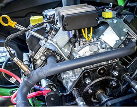 Kohler EFI gas engine
To maximize fuel economy and lower operating cost, the 2400 PrecisionCut™ Triplex Mower features a KOHLER Command PRO® EFI ECH630 air-cooled gasoline engine.
- Engines featuring EFI technology operate more efficiently than carbureted engines, saving fuel while in both mow and transport mode.
- This V-twin engine offers 14.2-kW (19-hp) gross power (per SAE J1995 at 3600 rpm) for plenty of power while operating in a wide range of conditions, including verticutting.
For the operator, the EFI engine offers an easy-to-use starting system that operates just like a car and does not require a choke. Simply turn the key, the engine will start, and the operator is ready to go.
KOHLER and Command PRO are trademarks of Kohler Co.
Easy access fuel tank with fuel gauge keeps operator productive
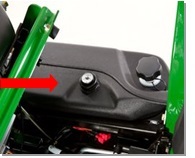 Fuel gauge and filler cap
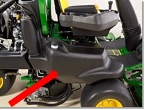 Twin-sheet design fuel tank
The fuel tank is a twin-sheet design to and meets fuel tank regulatory requirements and still has the capacity to get through a normal day without refueling. Easy access to the fuel cap and clear view of the fuel gauge keeps the operator productive all day.
Offset cutting units virtually eliminate triplex ring with a simple change in direction
 Offset cutting units
The innovative offset design staggers wheel tracks in the cleanup cut by simply changing direction of travel each day. This allows the turf an additional day to recover before being driven over again, and serves to minimize triplex ring and compaction.
The cutting units offset to the left-hand side of the machine. This provides good visibility to the center cutting unit. The traction unit frame is designed to maximize visibility down the left-hand side of the machine from the operator's point of view.
Optional weight transfer grass-catcher system transfers clipping weight to frame, rather than to cutting unit
Most golf courses want to mow the greens and collect the grass for a premium cut and even and smooth appearance. The most challenging concern with catching grass with a greens mower is that as the grass catcher fills with material, its weight is transferred to the cutting unit. This problem is multiplied with a riding greens mower because there are three cutting units and grass catchers collecting different amounts of grass, meaning different weights are applied to the three cutting units.
If the weight cannot be removed from the grass catchers, the different weights can cause different heights of cut with each cutting unit, leaving poor playing conditions and after-cut appearance. This is especially noticeable through undulations of a green and on the clean-up pass. The grass catchers on the riding greens mowers have been designed for optimum catching efficiency while maintaining a consistent, effective height of cut.
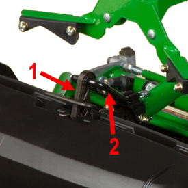 Grass catcher clip (1) and lift arm bracket (2)
The exclusive John Deere grass catcher transfers approximately two-thirds of the weight to the vehicle's lift arm. This helps maintain a more-consistent cutting height to ensure a uniform cut across all three cutting units.
The front grass catchers can be removed and installed with one hand because of an innovative clip system. The clip secures the catcher to an adjustable bracket on the lift arm, transferring weight from the catcher to the lift arm as clippings accumulate in the catcher.
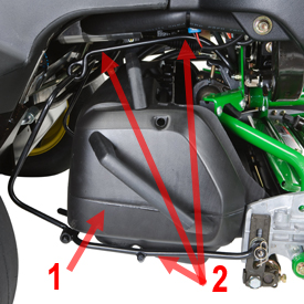 Rear grass catcher (1) and bail system (2)
The rear grass catcher mounting system simplifies removal and installation of the rear grass catcher and reduces effort.
The retaining bail system for the rear grass catcher also uses the exclusive John Deere design to transfer the weight of the grass catcher to the lift arm.
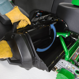 Rear grass catcher
The grass catcher can be easily removed, without spilling the clippings, by rotating the grass catcher back toward the front of the machine until the front grass catcher lip is above the cutting unit side plate. Then, simply pull it out to the side. This can be accomplished with the cutting unit in the raised or lowered position.
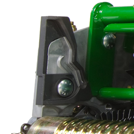 Grass catcher channel
A channel in the cutting unit side frames guides the grass catcher onto the cutting unit. The channel in the castings ensures the grass catcher lip maintains its relationship with the cutting unit when following undulations, providing for better grass catching efficiency.
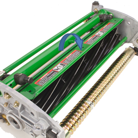 Adjustable top shield
Adjustable cutting-unit top shields also ensure that grass is thrown into the back of the catcher, even as the reel diameter decreases due to wear. The catchers are shaped and vented to allow the air from the reel to escape while retaining the clippings.
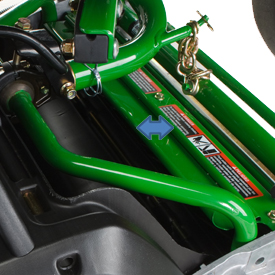 Top-shield extension for dry conditions
Extensions for the cutting-unit top shields are for use in dry conditions to maximize the flow of dry clippings into the grass catcher. If mowing predominantly in wet-turf conditions, remove the cutting unit shield extensions to reduce buildup and accumulation of clippings on the front of the grass catcher.
Consistent height of cut through contour following, weight transfer, and cutting-unit suspension
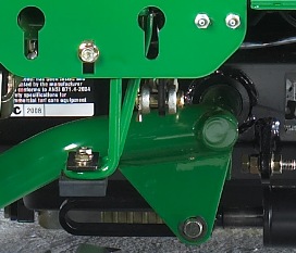 Lift-arm design
The cutting-unit suspension and lift arms are designed with down stops for the lift arms to rest on when the cutting units are lowered to mow. This transfers the weight of the lift arms onto the traction unit frame rather than adding weight to the cutting unit.
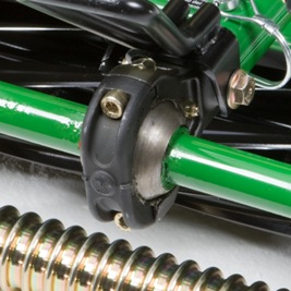 Ball-joint mounting design
The cutting-unit mounting system has a ball-joint swivel designed to allow the cutting unit to float independently of the lift arm. This design minimizes scalping and promotes a consistent height of cut by allowing the cutting unit to easily follow ground contours and steer in turns.
The cutting units can be easily and quickly removed from the lift arms by pulling the quick pin located behind the ball swivel joint and disconnecting the cutting unit support chain from the lift arm. This disengages the cutting unit assembly from the lift arm for service.
The cutting-unit drive motor also has a Quik-Tatch system that allows the technician to quickly remove the motor from the cutting unit for service. Simply loosen the mounting bolt that secure the motor to the bearing housing and twist the motor a quarter turn to remove.
Standard rollover protective structure (ROPS) with seat belts meets ISO 21299 standards
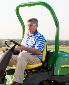 ROPS with seat belt
A ROPS and retractable seat belt are standard equipment on the 2400 PrecisionCut™, 2550 PrecisionCut, and 2550 E-Cut™ Hybrid Triplex Mowers. The ROPS meets ISO21299 standards.
Easy service access to minimize time to perform daily maintenance tasks
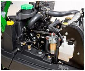 Daily service checks
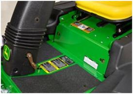 Access panel
Several serviceability features were incorporated into the design of the 2400 and 2550 PrecisionCut™ Triplex Mowers to make routine checks and adjustments as easy as possible.
Features include:
-
Good visibility to components, with a tilt-back hood and tilt-up seat platform. With the hood and seat platform in the raised position, access and visibility to the components underneath is very good.
- All daily service checks — engine oil level, air restriction indicator, engine coolant level (2550 only), and hydraulic oil level — are made from the left side of the machine.
- Quick-attach cutting units — one pin located at the front of the lift arms removes the cutting units from the traction unit with no tools.
- Quick-attach cutting unit motors — just loosen the two hold-down nuts, twist the motor, and pull it out away from the cutting unit.
- Remote grease fittings for the front lift arms are located on the front hydraulic fitting bulkhead. These remotely mounted fittings allow ease of lubrication for the front lift arm pivot pins.
- Electronic controller that provides service diagnostics by means of lighted circuits.
- There is also an access panel on the operator platform that can be easily removed to provide access to the backlap valve and battery.
Smooth and turf tire options to meet a variety of mowing conditions and areas
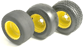 Smooth and turf tire options shown
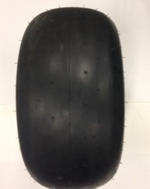 Balloon-rounded tire option
There are four tire options:
- 18x10.50-10 2-ply smooth tires are recommended for those who want the minimum amount of ground compaction. These tires have a large footprint to spread the weight of the vehicle over a larger area. This tire also lowers the overall height of the machine and reduces ground clearance of the cutting units. Compensation for ground clearance can be made by adjusting the cutting unit chain on the back of the cutting unit.
- 20x10-10 4-ply rated balloon-rounded smooth tires are recommended for those who want maximum ground clearance, increased ply rating and desire to use a more rounded tire. The 4-ply side wall rating has recommended operating tire pressure of 103 kPa (1.03 bar) (15 psi). Increased pressure may leave marks in softer turf conditions.
- 20x10-10 2-ply smooth tires are recommended for those who want maximum ground clearance while operating at the lower tire pressure of 83 kPa (0.83 bar) (12 psi).
- 20x10-10 4-ply rated smooth tires are recommended for those who want maximum ground clearance and increased ply rating. The 4-ply sidewall rating has recommended operating tire pressure of 103 kPa (1.03 bar) (15 psi). Increased pressure may mark in softer turf conditions.
- 20x10-10 turf tires are for those who need additional traction for mowing more difficult areas, such as elevated tees or fairways.
Each of these tire options includes a complete set of three tires and wheels that are all the same size. (This includes the turf tires, which come as a set of three treaded tires.)
55.9-cm (22-in.) cutting unit rear-attaching-point yoke kit for fairways, surrounds, and tees
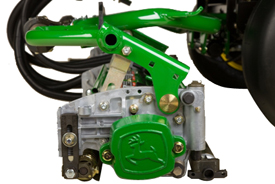 Rear attaching yoke
Low weight and compaction of a riding greens mower with the mowing system of a fairway mower equals great quality of cut in fairways and surrounds.
Many golf courses want to mow their fairways and other areas with riding greens mowers as a way to decrease compaction of the turf. However, the front-attaching-point yoke system used for greens is not the ideal solution for other areas due to the mowing speed, and the terrain is not as smooth as a green.
The 55.9-cm (22-in.) cutting unit rear-attaching-point yoke kit attaches to the rear cutting unit to help keep the rear roller on the ground consistently in undulating terrain. This also substantially improves cut quality by maintaining a consistent height of cut in virtually any condition. Rather than pushing the cutting unit through the turf, the yoke system pulls the cutting unit through the turf keeping the back end of the cutting unit engaged with the turf.
14-blade reel lowers frequency of clip
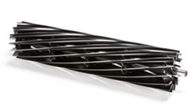 14-blade reel

Using the 14-blade reel on greens mowers will lower the frequency of clip and also provide a clean, smooth cut. It can increase the playability of the putting surface and greens speed.
Frequency of clip (FOC) is defined as the distance traveled between consecutive cuts. In other words, it is how far the machine moves from the time one blade passes across the bedknife until the next blade passes. The lower the frequency of clip, the less distance that is traveled until the next blade passes.
There is a point of diminishing returns when it comes to frequency of clip. The less distance the mower travels between consecutive cuts, the more times the same grass blade is going to be impacted by the reel. Too low a frequency of clip can cause bruising of the turf - especially in the overlap from pass to pass.
Frequency of clip is often used as a measurement of cut quality, however there are other key factors that attribute to gaining good quality of cut. The factors that lead to good cut quality are:
- Geometry of the cutting unit
- Sharpness of reels and bedknife
- Proper cutting-unit setup (parallel and bedknife-to-reel clearance)
- Height of cut (HOC) (effective versus bench HOC)
- Bedknife selection
- Roller selection for the turf conditions
- Turf conditions
The geometry of John Deere cutting units makes the optimum range for frequency of clip between 0.160 in. (4.064 mm) and 0.190 in. (4.824 mm) for walk greens mowers. This is where the technology of the PrecisionCut™ walk greens mowers excels and provides a superior cut and after-cut appearance.
Machines |
14-blade reel part number |
Minimum FOC |
Minimum FOC with AMT2865* |
180SL PrecisionCut Walk Greens Mower |
TCA23624 |
3.58 mm (0.141 in.) |
3.12 mm (0.123 in.) |
220SL PrecisionCut Walk Greens Mower |
TCA23623 |
3.58 mm (0.141 in.) |
3.12 mm (0.123 in.) |
*Frequency speed-up kit
Optional direct mount front grass-catcher system easy to install and remove
The optional direct mount front grass catchers provide the choice of systems to meet the needs on your golf course.
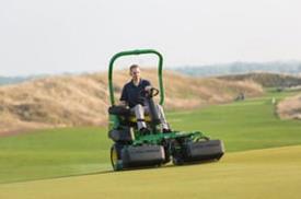 Front grass catcher
The grass catcher is mounted directly to the front cutting unit using a similar design as the SL Walk Greens Mowers.
This provides quick access for the removal and installation of the grass catcher as well as superior ground following and collection due to position of the catcher to the cutting unit.
It is recommended that catchers be emptied after each green during normal and heavy growth times to reduce weight on the cutting unit.
The direct mount grass catchers will fit model year 2009 to current 2500B and 2500E E-Cut Riding Greens Mowers with Quick-Adjust 5 (QA5) cutting units, as well as 2400 PrecisionCut™, 2550 PrecisionCut, and 2550 E-Cut™ Hybrid Triplex Mowers.
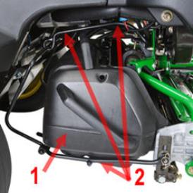 Rear grass catcher (1) and bail system (2)
The rear grass-catcher mounting system simplifies removal and installation of the rear grass catcher and reduces effort.
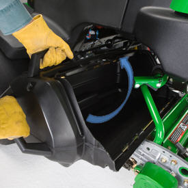 Rear grass catcher
The grass catcher can be easily removed without spilling the clippings by rotating the grass catcher back toward the front of the machine until the front grass catcher lip is above the cutting unit side plate. Then, simply pull it out to the side. This can be accomplished with the cutting unit in the raised or lowered position.
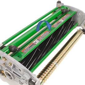 Adjustable top shield
Adjustable cutting-unit top shields also ensure that grass is thrown into the back of the catcher, even as the reel diameter decreases due to wear. The catchers are shaped and vented to allow the air from the reel to escape while retaining the clippings.
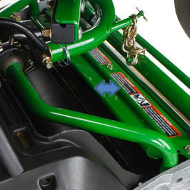 Top-shield extension for dry conditions
Extensions for the cutting-unit top shields are for use in dry conditions to maximize the flow of dry clippings into the grass catcher. If mowing predominantly in wet-turf conditions, remove the cutting unit shield extensions to reduce buildup and accumulation of clippings on the front of the grass catcher.
Larger, 63.5-mm (2.5-in.) front grooved disc roller compatible with fairway tender conditioner (FTC) and Greens Tender™ conditioner attachment for 55.9-cm (22-in.) Quick-Adjust 5 (QA5) reel cutting units
 Grooved disc roller
The grooved disc roller can be used with 55.9-cm (22-in.) QA5 cutting units, in combination with the Greens Tender Conditioner and FTC, to provide additional roller options for fairway, tees, and approach areas.
The increased diameter improves the durability over smaller rollers, and it features hardened discs for improved wear which retains spring tension for reduced maintenance, making it an ideal roller for fairway, tee, and approach mowing.
Specifications
Key Specs
| Number of cylinders | Two |
|---|---|
| Displacement | 694 cc 42.4 cu in. |
| Mowing speed | Adjustable mow stop: 0-7.1 km/h 0-4.4 mph |
| Traction drive | Hydrostatic, two-pedal control |
| Mowing position width | 157.5 cm 62 in. |
| Cutting unit size, in. (cm) | Quick Adjust QA5 floating: 55.9 cm 22 in. |
| Clip frequency | For 14 blade: 0.541 mm/km/h 0.034 in./mph With 11-blade reel: 0.689 mm/km/h 0.044 in./mph With 7-blade reel: 1.082 mm/km/h 0.069 in./mph |
| Height of cut | With 51-mm (2-in.) front roller: 2.0-19.0 mm 0.078-0.75 in. With 76 -mm (3-in.) fromt roller: 16-32 mm 0.625-1.25 in. |
| Number of blades | 7, 11, or 14 blades |
| Operator ear | 80 dBA |
Engine
| Type | Gas model KOHLER® ECH630 EFI gas with electronic throttle body |
|---|---|
| Horsepower | Gas horsepower At 3600 rpm: 14.2 kW 19 hp Engine manufacturer gross power, tested in accordance with SAE J1940 / J1995 |
| Air cleaner | Foam precleaner with paper element |
| Cooling | Oil filter Full-flow filter Engine oil capacity With filter: 1.9 L 2 U.S. qt Pressurized lubrication system Standard Number of cylinders Two Displacement 694 cc 42.4 cu in. Air |
Electrical System
| Charging system | Flywheel, alternator |
|---|---|
| Alternator capacity | 16 amp |
| Ignition | Capacitor discharge ignition (CDI) |
| Battery type | BCI group 40 maintenance-free: 12 V |
| Starter | Electric (solenoid shift) |
Vehicle Specifications
| Wheels and tires | Front/rear 18x10.5-10, 2-ply, smooth (low compaction) 20x10-10, 2-ply or 4-ply, smooth or 20x10-10, 2-ply, turf |
|---|---|
| Brakes | Single-pedal, 2-wheel disc brakes |
| Mowing speed | Adjustable mow stop: 0-7.1 km/h 0-4.4 mph |
| Transport speed | 0-12.9 km/h 0-8 mph |
| Reverse speed | 0-4.8 km/h 0-3 mph |
| Ground clearance with catcher | 10.2 cm 4 in. |
| Fuel tank capacity | In a single tank: 29.5 L 7.8 U.S. gal. |
| Muffler | Horizontal discharge below frame |
| Hydrostatic drive system capacity | 28.8 L 7.6 U.S. gal. |
| Hydraulic reservoir capacity (only) | 20.4 L 5.4 U.S. gal. |
| Ground drive, reel drive | Drive wheels Front Traction drive Hydrostatic, two-pedal control Reel drive Hydraulic |
| Pump | Three-section gear |
| Reel control valves | Electrohydraulic, one valve reel on-off and one valve raise-lower |
| Filtration | 10-micron |
Operator Controls
| Steering | Hydrostatic, adjustable steering column |
|---|---|
| Reel drive and reel lift | Right-hand operated (optional foot-lift controls) |
| Throttle | Right hand |
| Park brake | Right foot |
| Hydrostatic speed control | Forward Right foot Reverse Right foot |
| Ignition | Key start and shutoff |
| Glow plug switch and indicator light |
Instrumentation
| Engine oil pressure | Light-emitting diode (LED) warning light |
|---|---|
| Alternator | LED warning light |
| Hydraulic oil temperature | LED warning light |
| Engine coolant temperature | LED warning light |
| Hourmeter | Digital |
Electrical and Safety System
| Diagnostics | |
|---|---|
| Safety Interlocks |
Weights and Dimensions
| Wheelbase | 129.5 cm 51 in. |
|---|---|
| Tread width | 101.5 cm 40 in. |
| Mowing position width | 157.5 cm 62 in. |
| Turning radius, uncut circle | 45.7 cm 18 in. |
| Weight (full fluids, no operator or fuel) | 559.2 kg 1233 lb |
| Height | With ROPS: 195.6 cm 77 in. |
Cutting Units
| Number | Three - offset design |
|---|---|
| Size, in. (cm) | QA5 floating: 55.9 cm 22 in. |
| Backlapping | Standard on-board micro-backlapping and reel speed control |
| Clip frequency | For 14 blade: 0.541 mm/km/h 0.034 in./mph With 11-blade reel: 0.689 0.044 in./mph With 7-blade reel: 1.082 mm/km/h 0.069 in./mph |
| Front rollers | Optional smooth, grooved, or spiral: 5.1 cm 2 in. |
| Reel diameter | 12.7 cm 5 in. |
| Bedknife adjustment | Bedknife-to-reel |
| Height of cut | With 51-mm (2-in.) front roller: 2.0-19.0 mm 0.078-0.75 in. With 76 -mm (3-in.) fromt roller: 16-32 mm 0.625-1.25 in. |
| Number of blades | 7, 11, or 14 blades |
| Mower lift | One cylinder for front two units; one cylinder for rear unit |
| Reel speed | Adjustable |
Certification
| Number | ANSI B71.4-2017 |
|---|---|
| ROPS | Two-post SAE J21294 rollover protective structure with seat belts meets ISO 21299 standards |
| Engine | Meets CARB and EPA |
Sound Levels
| Operator ear | 80 dBA |
|---|---|
| Measuring standard | ISO 11201 |
| Attachments installed | Greens Tender™ conditioners and power brushes, reels engaged |
Additional information
| Date collected | 11-Feb-2020 |
|---|
Contact Us
-
325 Walt Messick Road
Harrington, Delaware 19952
Phone: (302) 398-3729
Toll Free: (800) 237-1272
